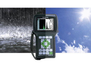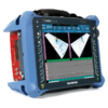
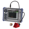


Ultrasonic Flaw DetectorEPOCH 650
EPOCH 650
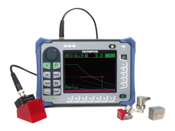
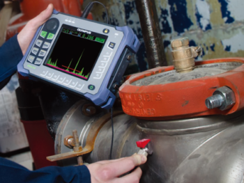
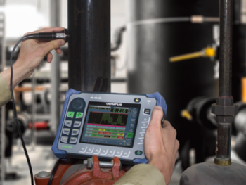
Versatile and Rugged Flaw Detector

• Compact and Rugged
• Powerful Data Reporting
• Intuitive Interface
• EN12668-1 Compliant
Key Features
• Designed to meet the requirements of EN12668-1
• PerfectSquare™ tunable square wave pulser
• Full screen A-scan mode
• Digital high dynamic range receiver
• Thirty digital filters for enhanced signal-to-noise ratio
• 2 kHz PRF for rapid scanning
• Knob or navigation pad adjustment configurations
• Large, full VGA sunlight readable display
• 15+ hours of battery life
• Standard dynamic DAC/TCG and onboard DGS/AVG
• Multiple on-board report formats
• MicroSD memory card for data transfers
• Optional Corrosion Module software with Encoded B-scan
• USB On-The-Go (OTG) for PC communication
• Alarm and VGA outputs
• Optional analog output
| Instrument Inputs/Outputs | USB Ports | USB On-The-Go (OTG) |
|---|---|---|
| RS-232 Port | Yes | |
| Video Output | VGA output standard | |
| Analog Output | 1 analog output (optional), Selectable 1 V/10 V Full Scale, 4mA max | |
| Alarm Output | 3 alarm outputs, 5 V TTL, 10 mA | |
| Trigger I/O | Trigger input, 5V TTL; Trigger output, 5V TTL, 10 mA max |
|
| Encoder Inputs | 1-axis encoder line (quadrature – Corrosion Module mode only) | |
| Environmental Ratings | IP Rating | Designed to meet the standards of the Ingress Protection (IP) rating number IP67 (navigation pad version) or IP66 (knob version) per IEC 60529-2004 (Degrees of Protection provided by enclosures – IP Code).The product design was confirmed to meet the IP rating by means of Olympus internal design verification test process that occurs prior to the release of the product to production. |
| Explosive Atmosphere | Safe operation as defined by Class I, Division 2, Group D, as defined in the National Fire Protection Association Code (NFPA 70), Article 500, and tested using MIL-STD-810F, Method 511.4, Procedure I. | |
| Shock Tested | MIL-STD-810F, Method 516.5 Procedure I, 6 cycles each axis, 15g, 11 ms half sine. | |
| Vibration Tested | MIL-STD-810F, Method 514.5, Procedure I, Annex C, Figure 6, general exposure: 1 hour each axis | |
| Operating Temperature | –10 °C to 50 °C (14 °F to 122 °F) | |
| Battery Storage Temperature | 0 °C to 50 °C (32 °F to 122 °F) | |
| General | Overall dimensions (W x H x D) | 236 mm x 167 mm x 70 mm (9.3 in. x 6.57 in. x 2.76 in.) |
| Weight | 1.6 kg (3.5 lb), including lithium-ion battery | |
| Keypad | English, International, Japanese, Chinese | |
| Languages | English, Spanish, French, German, Japanese, Chinese, Portuguese, Russian | |
| Transducer connections | BNC or Number 1 LEMO | |
| Data storage | 100,000 IDs onboard, removable 2 GB MicroSD card (standard) | |
| Battery type | Single lithium-ion rechargeable standard | |
| Battery life | 15 h to 16 h (lithium-ion) | |
| Power requirements | AC Mains: 100 VAC to 120 VAC, 200 VAC to 240 VAC, 50 HZ to 60 Hz | |
| Display type | Full VGA (640 x 480 pixels) transflective color LCD, 60 Hz update rate | |
| Display dimensions (W x H, Diag.) | 117 mm x 89 mm, 146 mm (4.62 in. x 3.49 in., 5.76 in.) | |
| Pulser | Pulser | Tunable Square Wave |
| PRF | 10 Hz to 2000 Hz in 10 Hz increments | |
| Energy settings | 100 V, 200 V, 300 V or 400 V | |
| Pulse width | Adjustable from 25 ns to 5,000 ns (0.1 MHz) with PerfectSquare™ technology | |
| Damping | 50, 100, 200, 400 Ω | |
| Receiver | Gain | 0 to 110 dB |
| Maximum input signal | 20 V p-p | |
| Receiver input impedance | 400 Ω ± 5% | |
| Receiver bandwidth | 0.2 MHz to 26.5 MHz at -3 dB | |
| Digital filter settings | Thirty digital filter sets standard Seven EN12668-1:2010 compliant filters (0.2-10 MHz, 2.0-21.5 MHz, 8.0-26.5 MHz, 0.5-4 MHz, 0.2-1.2 MHz, 1.5-8.5 MHz, 5-15 MHz) |
|
| Rectification | Full-wave, Positive Half-wave, Negative Half-wave, RF | |
| System linearity | Horizontal: ± 0.5% FSW | |
| Resolution | 0.25% FSH, amplifier accuracy ± 1dB | |
| Reject | 0 to 80% FSH with Visual Warning | |
| Amplitude measurement | 0 to 110% full screen height with 0.25% resolution | |
| Measurement rate | Equivalent to PRF in all modes | |
| Calibration | Automated calibration | Velocity, Zero Offset Straight Beam (First Backwall or Echo-to-Echo) Angle Beam (Soundpath or Depth) |
| Test modes | Pulse Echo, Dual, or Through Transmission | |
| Units | Millimeters, inches, or microseconds | |
| Range | 3.36 mm to 13,388 mm (0.132 in. to 527.10 in.) @ 5,900 m/s (0.2320 in./μ) | |
| Velocity | 635 m/s to 15240 m/s (0.0250 in./µs to 0.6000 in./µs) | |
| Zero offset | 0 µs to 750 µs | |
| Display delay | -59 mm to 13,401 mm (-2.320 in. to 526.97 in.) @ longitudinal velocity in steel | |
| Refracted angle | 0° to 90° in 0.1° increments | |
| Gates | Measurement gates | 2 fully independent gates for amplitude and TOF measurements |
| Gate start | Variable over entire displayed range | |
| Gate width | Variable from Gate Start to end of displayed range | |
| Gate height | Variable from 2 to 95% full screen height | |
| Alarms | Positive and Negative Threshold, Minimum Depth (Gate 1 and Gate 2) | |
| Measurements | Measurement display locations | 5 locations available (manual or auto selection) |
| Gate (1, 2) | Thickness, Soundpath, Projection, Depth, Amplitude, Time-Of-Flight, Min./Max. Depth, Min./Max. Amplitude | |
| Echo-to-Echo | Standard Gate 2-Gate 1, Optional IF Gate Tracking | |
| Other measurements | Overshoot (dB) value for DGS/AVG, ERS (equivalent reflector size) for DGS/AVG, AWS D1.1/D1.5 A, B, C and D values, Reject Value, Echo to RefdB values | |
| DAC/TCG | Standard | |
| DAC points | Up to 50 points, 110 dB dynamic range | |
| Special DAC modes | Custom DAC (up to 6 curves), 20-80% View | |
| Curved surface correction | Standard OD or Bar correction for Angle Beam measurements | |
| Corrosion (optional) | Zero-cross measurement algorithm, V-Path correction, Single or Echo-to-Echo, Encoded B-scan |